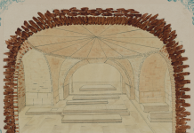
The perspective construction was carried out from the same observation point in the plan by the method of projections to the vertical, along with individual distortions in the details (capital, base and proportions of the column, lantern, equidistant from. for the viewer, the columns are depicted in different sizes, etc.) the whole hall appears to be more spacious – deep and high than in reality. A sharper bend of the architrave and an excessive reduction in the height of the removed columns increase the depth of the hall and its scale in the perspective image.
The construction of the second image of the hall was carried out from the point O in the plan at the angles of view. The construction scheme remained the same as in the previous case. The vertex of the projection surface trace is located in the plan on a ray passing through the center of the depicted semicircle and the location of the viewer. This position of the projection surface allows in the axis, and the values. Connecting the obtained points A and B with a straight line, we get a perspective projection of the plane of the facade of the building. Similarly, on the axis, but already on the lower scale, we find the values. The perpendiculars placed at these points before the intersection with the curve will determine the perspective projection of the second plane of the facade of the building. In order to bring the perspective projections of both facades of the building to the same scale and complete the construction of a perspective image of the building in general terms, we will make the following simple construction. Let us draw, respectively, the straight line AD parallel, and the diagonal of the trapezoid AD parallel to the diagonal, which at the intersection will determine the position of the point D. By lowering the perpendicular from point D, we get a perspective image of a parallelepiped into which the volume of the building fits, followed by a detailed breakdown and drawing in known ways.
Verticals can get a slight perspective slope to the central axis in the future only with a fragmentary image of the upper parts of buildings at vertical viewing angles of more than 45°, when the drawing already feels a promising reduction of horizontal segments and a slight perspective slope of the verticals at a fixed observation point. Only the discrepancy between the features of visual perception, from nature, can explain the fact that the use of projections on an inclined plane in the construction of perspective images with its excessive perspective cuts and vertical angles has not been widespread in the practice of architectural design.
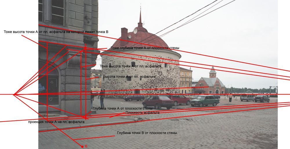
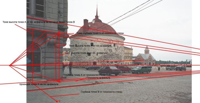
Verticals in most cases are depicted in perspective as vertical, whereas in similar conditions and at the same angles of view, horizontal lines receive quite definite and significant perspective slopes to the horizon. In order to correctly reflect these abbreviations in perspective constructions, it is necessary to identify their actual magnitude and measure. This can be established by analyzing drawings from nature, made taking into account the position of the drawing and measuring the object. All further conclusions and suggestions are based on the experiments and observations carried out by the authors of this work. These conclusions are confirmed by a number of drawings from architectural objects, which makes it possible to determine the nature and degree of perspective abbreviations perceived by the viewer and transmitted in the drawing. All drawings were carried out to complete completeness. For greater clarity, only individual fragments of the drawing are schematically given, which show the nature of perspective reductions and the degree of angle of one of the facades of the building, the image will correspond.
